The goal of this tutorial is to create a simple Beowulf cluster using Parallella boards. After completing these instructions, you should have a simple Parallella Cluster with N nodes. In the examples that follow, N=4. However, the tutorial can be used to create clusters of any size N.
These instructions are adapted from the raspberry pi cluster instructions provided by Dr. Simon Cox from the University of Southampton. Unlike those instructions, I designed this tutorial to enable students to assemble a working parallella cluster within one hour. This page is based off of the original cluster tutorial I wrote in November 2014.
One of the most common parallel patterns is the Master-Worker pattern. In this pattern, a master process (or node) is responsible for creating a set of tasks and delegating them to some N-1 workers. All N nodes then complete the work and report the final results back to the master.
In the case of our Parallella cluster, communication will be taken care of using the MPI library. All of our work will be done on the master node; we will write and execute our MPI programs there. Our master node will then use the MPI library to communicate with the other nodes in our cluster, and complete the work in parallel.
Are you ready? Let’s get started!
What you will need
This tutorial assumes that you bought a Parallella Desktop Edition and have access to a Windows machine. If you haven’t set up your Parallella yet, please see my instructions for initial set up.
- A laptop (with SD card reader)
- N=4 Parallella boards, each w/power supply
- N=4 cat5 ethernet cables, microSD cards (8GB preferred for inital setup; see notes)
- a switch with access to the Internet (or a router)
- case parts for each board (2 base boards, 4 singe connectors, 4 double connectors)
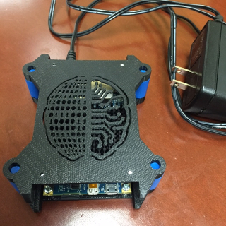
The picture above shows what each individual Parallella board should look like when set up. Begin by setting up only two of the boards. Keep the SD cards and cat5 cables aside for now.
Setting up the Master Node
Recall that the microSD card is used to house the operating system on our Parallella. To set up our master node, we first install an image of our desired operating system. In essence, an image allows us to get a set of desired software onto our system quickly and relatively painlessly. We provide an image for you, called par-master.img that you can download from this link.
- From the Web: Download & Install Win32 Disk Imager (you may need to use admin privileges).
- Download the par-master.img file.
- Insert microSD card + adapter into the SD card reader slot.
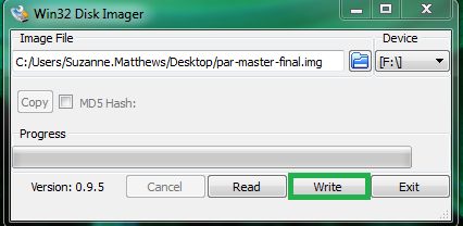
- Using Win32 Disk Imager, select the drive the SD card is in (usually the F drive). Be absolutely sure that the selected drive is the one associated with the SD card!
- Use the folder icon to navigate to where you downloaded the image. Click “write”. This process may take a few minutes.
- Once the process is done, safely eject the SD card and boot up your
Parallella board. The login is
linaroand the password islinaro. - Use the cat5 cable to connect your Raspberry Pi to your router.
Type in
ifconfigto get your IP address. You should see something like192.168.1.123. The last 3 numbers will likely be different on your machine. It should NOT be 255! - Replace the IP address in the provided
machine_filefile in thempi_testing/directory by using the following command (replace192.168.1.123with the IP address you found in the previous step). Next,cdinto thempi_testingdirectory.
echo '192.168.1.123' > ~/mpi_testing/machine_file
cd ~/mpi_testing/
- Ensure that MPI works by typing in the following command:
mpiexec –machinefile machine_file –n 2 ~/mpich2_build/examples/cpi

Process 0 of 2 is on linaro-nano
Process 1 of 2 is on linaro-nano
pi is approximately 3.1415926544231318, Error is 0.0000000008333387
If you make it this far, great job! You are ready to create worker nodes.
Setting up the worker nodes- Part I
Our master node will “communicate” with our worker nodes using the Secure Shell (SSH) protocol. In this next step, we need to give our master node the proper login credentials so it can seamlessly connect to the worker nodes as needed. To accomplish this, we will add ssh credentials to our master node, and test our setup using a new worker node. All the commands below (unless otherwise noted) are typed on the master node.
- Create an image for your new worker node by repeating the steps 3 in the previous section. Connect the new worker node to the router and boot it up.
- On the master node, generate an ssh key by typing in the following:
cd
ssh-keygen –t rsa –C 'linaro@linaro-nano'
Use the default location. Do NOT enter a passphrase!
- Determine the IP address of the worker node. Visit your router’s page using a web browser (192.168.1.1) to determine the worker’s IP. You can test that you can reach the machine by typing:
ping 192.168.1.124
where the above IP is the worker node’s IP. If a
route to the machine exists, you will get a response. Be sure to check your
connections to the router to ensure that the master node is plugged into the
1 location, and the worker node is plugged into the 2 location.
- Copy the log-in credentials to your worker node by typing in the following:
cat ~/.ssh/id_rsa.pub | ssh linaro@192.168.1.124 'cat >> .ssh/authorized_keys'
Where 192.168.1.124 should be replaced with the IP of the worker node.
- When this is done, ensure you can ssh into the worker node without the need for any credentials by typing in the following:
ssh linaro@192.168.1.124
You should automatically be logged on to the machine, without being asked for any passphrases or passwords. If this doesn’t happen, you did something wrong, and will need to repeat the previous steps in this section.
- Let’s change the hostname for this machine. Type in the following command:
sudo nano /etc/hostname
to launch the nano editor. Replace what’s there with something like worker001.
Make the same change to the last line of the /etc/hosts/ file. Restart the
machine to see changes:
sudo shutdown -r now
This will restart the worker node, and kick you out of the SSH session.
- Next, let’s repeat the test from the previous section.
cdinto the thempi_testingfolder and edit the filemachine_fileand add the IP of your new worker node:
echo '192.168.1.124' >> ~/mpi_test/machine_file
cd ~/mpi_test/
Rerun the MPI test:
mpiexec –f machine_file – n 2 ~/mpich2_build/examples/cpi
You should get something like the following:
Process 0 of 2 is on linaro-nano
Process 1 of 2 is on worker001
pi is approximately 3.1415926544231318, Error is 0.0000000008333387
If the above works, great job! You are ready to create additional worker nodes! Unlike our test from the previous section, we are now running our test on multiple nodes!
Setting up the worker nodes - Part II
Our worker node now contains the proper SSH credentials our master node needs to login seamlessly. To allow our master node to be able to log in to other nodes, we must copy the image of the worker node we just created onto the other worker nodes we plan to create.
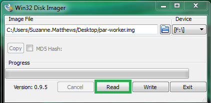
- Place the SD card of the worker node you created in the previous section into your laptop. Fire up Win32 Disk Imager.
- Type a path into the text box:
C:\path\to\Desktop\workerNode.img\where\path\to\Desktopis the path to your Desktop. Select the drive that contains the SD card. Click thereadbutton. This will copy the image that is on your SD card to your desktop.
Once the process is done, remove the SD card, and place it back into your worker node.
- Insert a new SD card. In Win32 Disk Imager, select the image you just wrote to your desktop. Ensure the SD card’s drive is selected in the window. Click ‘write’. This process may again take a while.

Repeat the previous step for each additional worker node.
- Once you are done, load the new SD cards into your other Parallellas, and
connect them to your router. Figure out the IPs for each,
sshin, and change their hostnames using the process outlined in the the previous section. You want each worker node to have distinct names. So, if you are creating two new worker nodes, you may want to name themworker002andworker003. Remember to restart the worker nodes in order to see the reflected changes! - Repeat the MPI test we did in the last two sections.
cdinto thempi_testingfolder, and editmachine_fileto include the IP addresses of the new worker nodes. Then, re-run the test:
mpiexec –f machine_file –n 4 ~/mpich2_build/examples/cpi
You should get something like the following:
Process 0 of 4 is on linaro-nano
Process 1 of 4 is on worker001
Process 3 of 4 is on worker003
Process 2 of 4 is on worker002
pi is approximately 3.1415926544231239, Error is 0.0000000008333307
Remember these can be out of order (so don’t worry about that). If everything above works, hooray! You are done!
Setting up a NFS shared hard drive
A drawback to the above system is that each node has its own local disk-space.
If we want to share files between the nodes, we will have to use something like
scp. With a large number of files, this can get very tedious. A better solution
is to set up a Network File System (NFS). We will mount a hard drive on the
master node. Each node on the network will then able to read/write files to
the hard drive over the network. Prior to beginning, make sure that you
reformat your selected external hard drive to a linux file system, such as
ext3 or ext4. You can easily do this using the gparted utility.
Step 1: Install requisite software
On all of nodes, install nfs-common and rpcbind packages:
sudo apt-get install nfs-common rpcbind
On just the master node, also install the nfs-server package:
sudo apt-get install nfs-server
Step 2: Mount the hard drive on the master node
After you attach your external HD to the powered USB hub, see where it is
located by using the fdisk command:
sudo fdisk -l
A huge amount of output will result. The external hard drive will usually be at
the end of this output. Mine is located at /dev/sda1.
Next, create a mount point and mount your hard drive. In the examples below,
our mount point is /mnt/nfs and the hard drive is located at /dev/sda1:
sudo mkdir /mnt/nfs
sudo chown -R linaro:linaro /mnt/nfs
sudo mount /dev/sda1 /mnt/nfs
Step 3: Export new filesystem
The /etc/exports file allows us to define which folders/files we wish to
share with others, and who we wish to share them with. Determine the IPs of
all the worker nodes on your network by visiting 192.168.1.1. In this
example, our master node has the IP 192.168.1.123 and our three worker nodes
have the IPs 192.168.1.124, 192.168.1.125 and 192.168.1.126 respectively.
Modify the /etc/exports file to include the following lines:
/mnt/nfs 192.168.1.124(rw,sync)
/mnt/nfs 192.168.1.125(rw,sync)
/mnt/nfs 192.168.1.126(rw,sync)
This indicates that each of our worker nodes have read/write access to the
shared drive located at /mnt/nfs, and all writes to the hd on the master
will be commited immediately to the network.
Reboot the master node, and all the workers.
Step 4: Mount the hard drive on all the nodes
When you reboot the machines, the hard drive will no longer be mounted. Let’s first remount the harddrive on the master node:
sudo mount /dev/sda1 /mnt/nfs
Next, ssh into each of the worker nodes. Check to make sure that we can see the mount point on the master:
showmount -e 192.168.1.123
You should see /mnt/nfs being listed, along with all the other worker node
IPs.
To mount the hard drive on the worker node, type the following:
sudo mount 192.168.1.123:/mnt/nfs /mnt/nfs
This mounts the /mnt/nfs folder on the master to your local /mnt/nfs folder.
Now, you should be able to read/write files to the hardrive!
Next steps: autofs?
You can easily wrap the mount command from step 4 in a script, to serially
mount the hard drive on all the workers. This is a workaround solution. Ideally,
we would want something like autofs to work, which will allow the drive to
be automatically mounted on all the workers on boot. Unfortunately, I have not
gotten autofs to work correctly, and modifying the /etc/fstab file causes
heartaches as well. Will put an update here if I end up figuring it out.
Building the case
Now we have N Parallellas networked together. Your setup probably looks like a mess. Let’s build a case for our new cluster. You can use whatever you wish, but we provide a 3D printed design that you may find attractive/convenient.
For a N node cluster, you will need at least:
- 2xN base boards and at least 4 connectors per layer. If you are planning to stack your board vertically, only four end connectors per level will be needed. If you are planning on building your cluster horizontally, you will need middle connectors. Sketch out your layout and print your part appropriately.
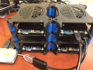
The following instructions are for a 2x2 configuration. This requres 8 base boards, 8 end connectors, and 6 middle connectors.
- Place boards in a 2x2 configuration. Place 2 middle connectors to connect the two base boards on each layer. Place end connectors in the holes on the end. Repeat with next layer, and finish by placing remaining 2 base boards on top. Finished cluster is shown below:
Troubleshooting
There are a number of problems you may face during setup. I’ve compiled a list of the most common issues, and ways to rectify them.
- Check and make sure that all the ip addresses in your machine_file are valid.
If not, fix your
machine_filewith the appropriate IPs. - Ensure that you can ssh into the worker nodes from the master nodes without needing a password. If you are asked to provide a password, that means the host’s ssh keys were not added to the worker’s set of authorized keys. Follow the steps in the “Setting up worker nodes” section. Reboot the worker node!
- Ensure that you can ssh from each worker node into the master node (this is an issue with some routers – does not appear to be a problem when connecting to a switch): Edit /etc/hosts.allow and add the following line:
sshd: ALL
- If you CAN ssh from each worker node into the master node, BUT require a
password to do so, you may need to add generate an ssh key for each worker
node and add it to the master’s list of known hosts. Replace
worker001with the name of each respective host, and the IP below with the master’s IP address:
cd
ssh-keygen –t rsa –C 'linaro@worker001'
cat ~/.ssh/id_rsa.pub | ssh linaro@192.168.1.123 "cat >> .ssh/authorized_keys"
Be sure to restart the master node when you are done.
- If it’s taking too long to build images for the worker nodes, consider using a smaller SD card to create the worker node image (I recommend 8GB). This will yield 8GB worker node images, which can be formatted onto a larger SD card. You can then expand the size of the image to fit the SD card. See the set up tutorial for more instructions.